Relay control via Arduino microcontroller¶
Automated power control over USB-serial (115200 baud): DUTs and rack infrastructure (cooler, PSU). The network switch is neither fed nor switched from this Arduino; it stays on mains continuously.
1. System overview¶
The Arduino Nano controls 11 channels over USB-serial. Device: /dev/arduino-relay (udev). The arduino_daemon.py daemon keeps serial open to avoid bootloader resets; arduino_relay_control.py talks to the daemon or the port directly.
| Range | Role |
|---|---|
| 0-7 | Electromechanical relays (8-ch module, 5 V, opto) for DUTs |
| 8-10 | SSR / Fotek: infrastructure (channel 8 wired no-load; cooler; PSU) |
2. Automatic PSU power-on¶
DUT relays (channels 0-7) switch the 12 V DC bus, which is powered by the PSU controlled on channel 10 (Fotek SSR). If the PSU is off, closing a DUT relay has no effect - there is no voltage on the bus.
arduino_relay_control.py handles this dependency automatically: any on command targeting channels 0-7 queries STATUS first and turns channel 10 ON if it is off. This applies to both the daemon path and direct serial.
| Scenario | Behavior |
|---|---|
on 0 with PSU already ON |
No-op on channel 10, turns on channel 0 |
on 0 with PSU OFF |
Turns on channel 10 first, then channel 0 |
on 8 or on 9 |
No PSU check (infrastructure channels, independent) |
on 10 |
Direct PSU control, no extra check |
This means tests via PDUDaemon (cmd_on: arduino_relay_control.py on %s) work even if the rack was powered down - the first DUT power-on automatically starts the PSU.
PSU is not turned off automatically
Turning off a DUT relay does not turn off the PSU. The PSU stays on until explicitly turned off (arduino_relay_control.py off 10 or all-off).
3. Hardware and channel map¶
Module and channel 10 PSU photos: Hardware catalog - Arduino relays and AC supply (channel 10).
3.1 Infrastructure (SSR)¶
| Channel | Pin | Device | Hardware | Logic |
|---|---|---|---|---|
| 8 | D10 | No load (CH1 on 4-ch SSR; signal wired on UTP) | 4-ch SSR module, CH1 | Active low |
| 9 | D11 | Booster AC cooler | 4-ch SSR module, CH2 | Active low |
| 10 | D12 | Power supply | Fotek SSR-25DA (standalone) | Active high |
Channel polarity
Channel 10: HIGH = ON. Channels 0-9: LOW = ON.
Per-channel AC box build (Omron CH1-CH4, Fotek): AC control box (lab build).
3.2 DUTs (mechanical relays)¶
| Channels | Pins | Hardware |
|---|---|---|
| 0-7 | D2-D9 | 8-channel electromechanical relay module (5 V DC, optocoupled) |
3.3 Module specifications¶
Manufacturer tables, load limits, and board data: Hardware catalog - Arduino relays.
4. Physical wiring (DUTs - DC power)¶
12 V DC cut by electromechanical relay (channels 0-7):
| Conductor | Path |
|---|---|
| 12 V+ (PSU) | PSU V+ → relay COM bus → NO contact → DUT DC+ |
| GND (PSU) | PSU GND → common GND bus → DUT GND (not switched) |
5. Signal wiring (UTP)¶
UTP Cat5e/6, ~2 m: signals and common GND.
| Pair | Color | Function | Arduino pin | Relay terminal |
|---|---|---|---|---|
| Orange | Orange | Channel 8 signal (CH1, no load) | D10 | CH1 (4-ch SSR) |
| White/Orange | GND | GND | DC- | |
| Green | Green | Cooler signal | D11 | CH2 (4-ch SSR) |
| White/Green | GND | GND | DC- | |
| Brown | Brown | PSU signal | D12 | Terminal 3 (Fotek) |
| White/Brown | GND | GND | Terminal 4 (Fotek) |
Electrical schematics (arduino - relays inside AC control box)¶
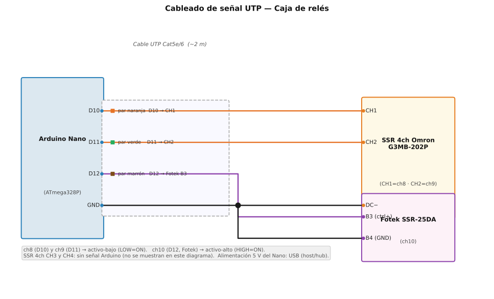
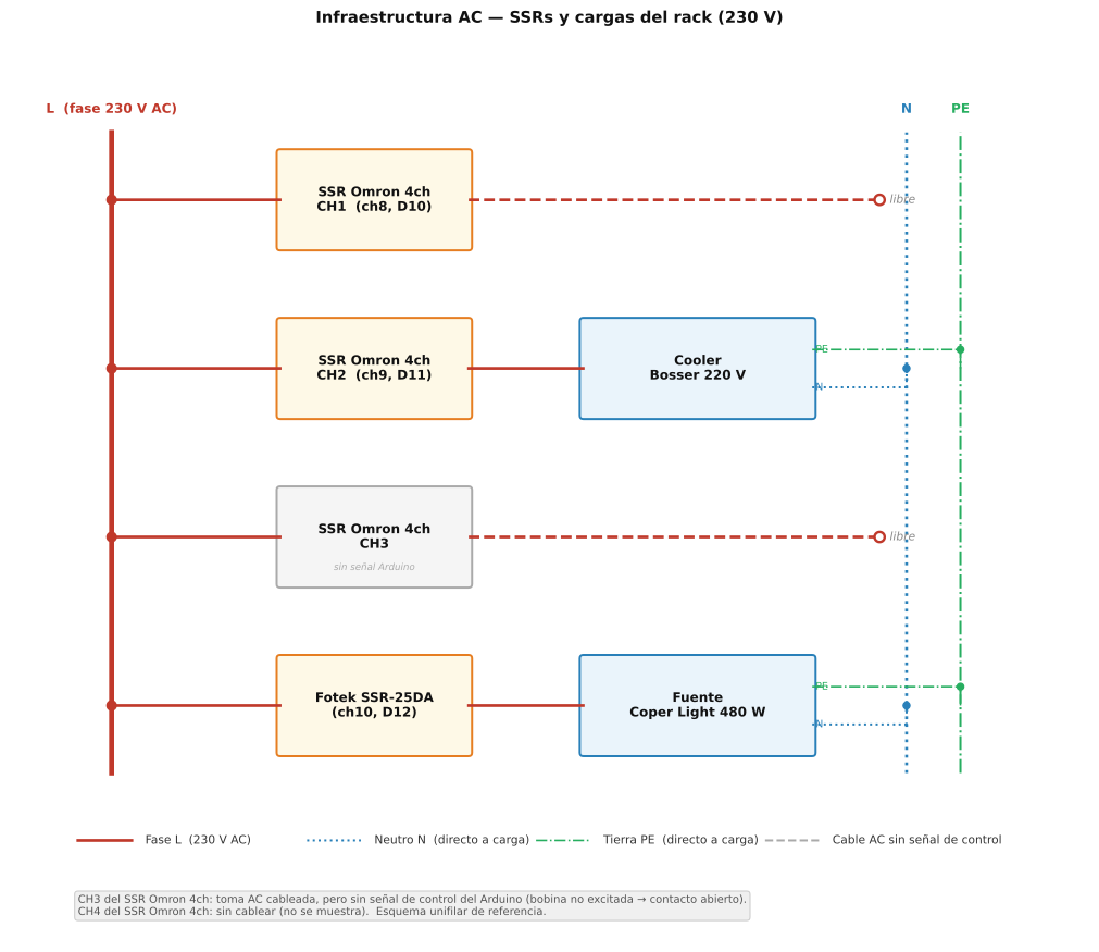
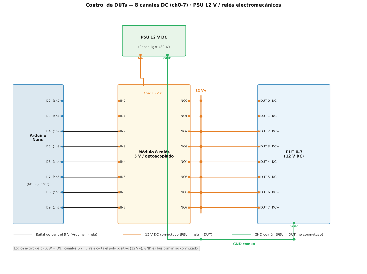
AC control box¶
Serial command channels are 0-10 (ON n, arduino_relay_control.py). On the Omron G3MB-202P, silkscreen CH1-CH4 map as below.
- Cmd ch = arduino sketch
- N/A = no Arduino output for that module channel
| Module | Omron CH | Cmd ch | Pin | AC box wired | Load | Arduino signal |
|---|---|---|---|---|---|---|
| G3MB-202P | CH1 | 8 | D10 | Yes | None | Yes |
| G3MB-202P | CH2 | 9 | D11 | Yes | AC cooler | Yes |
| G3MB-202P | CH3 | N/A | N/A | Yes | None | No |
| G3MB-202P | CH4 | N/A | N/A | No | None | No |
| Fotek SSR-25DA | Single | 10 | D12 | Yes | PSU (AC branch) | Yes |
Channels 0-9: active low. Channel 10: active high. Summary: §3.1 Infrastructure (SSR).
6. Serial commands¶
Baud rate: 115200 bps.
| Command | Description | Example |
|---|---|---|
ON n [n ...] |
Turn channel(s) on | ON 9 10 |
OFF n [n ...] |
Turn off | OFF 10 |
TOGGLE n [n ...] |
Toggle | TOGGLE 9 |
PULSE n ms |
Pulse ms | PULSE 0 500 |
ALLON / ALLOFF |
All on/off | |
STATUS |
State of 11 channels | |
HELP / ID |
Help / ID |
# With arduino_relay_control.py (uses daemon if running)
arduino_relay_control.py on 9 10
arduino_relay_control.py off 10
arduino_relay_control.py pulse 0 3000
arduino_relay_control.py status

# Direct serial (no daemon)
stty -F /dev/arduino-relay 115200 raw -echo && echo "ON 9 10" > /dev/arduino-relay
7. Arduino Relay Daemon (arduino_daemon.py)¶
Avoids Arduino reset when opening/closing the port: persistent serial connection, Unix socket /tmp/arduino-relay.sock. arduino_relay_control.py and PDUDaemon benefit when the service is enabled.
7.1 systemd service (recommended)¶
Unit source: configs/templates/arduino-relay-daemon.service → /etc/systemd/system/.
# From fcefyn-testbed-utils repo root:
sudo cp scripts/arduino/arduino_daemon.py /usr/local/bin/ && sudo chmod +x /usr/local/bin/arduino_daemon.py
sudo cp configs/templates/arduino-relay-daemon.service /etc/systemd/system/
sudo systemctl daemon-reload && sudo systemctl enable --now arduino-relay-daemon
7.2 Manual (testing)¶
./scripts/arduino/start_daemon.sh
# or: python3 scripts/arduino/arduino_daemon.py start --port /dev/arduino-relay
Daemon commands: start, stop, status. PID /tmp/arduino-relay.pid, socket as above, log /tmp/arduino-daemon.log with start_daemon.sh.
7.3 Self-healing after power events¶
Observed failure¶
After a power outage (or USB hub reset), the Arduino or its serial adapter re-enumerates. The kernel recreates /dev/arduino-relay, but the daemon keeps writing to the old file descriptor opened at startup.
| Symptom | Meaning |
|---|---|
systemctl status arduino-relay-daemon shows active (running) |
Process never exited |
arduino_relay_control.py status (or any relay command) fails with Input/output error (errno 5) |
Stale serial link |
| CI / Labgrid power commands fail | PDUDaemon cannot reach the relays |
Restart=on-failure alone does not fix this: systemd only restarts when the process exits. A zombie daemon stays alive with a dead FD until someone runs systemctl restart manually.
Recovery mechanisms¶
Three pieces work together after power outages and USB glitches:
| Mechanism | Where | What it does |
|---|---|---|
| Heartbeat | arduino_daemon.py |
Every 30 s of inactivity, sends ID to the Arduino. On I/O error, the daemon exits with code 1; Restart=on-failure starts a fresh process with a new serial FD. |
| BindsTo | arduino-relay-daemon.service |
Binds to dev-arduino\x2drelay.device. When the USB device disappears, systemd stops the service. It does not start it again when the device reappears. |
| SYSTEMD_WANTS | 99-serial-devices.rules (Arduino rule) |
When udev creates /dev/arduino-relay, it tells systemd to start arduino-relay-daemon.service. |
# Arduino rule (excerpt) - configs/templates/99-serial-devices.rules
SUBSYSTEM=="tty", ATTRS{idVendor}=="0403", ATTRS{idProduct}=="6001", ATTRS{serial}=="A5069RR4", \
  SYMLINK+="arduino-relay", ..., \
  TAG+="systemd", ENV{SYSTEMD_WANTS}="arduino-relay-daemon.service"
| Scenario | Heartbeat | BindsTo | SYSTEMD_WANTS |
|---|---|---|---|
| Stale FD, device node still present | Detects and exits | - | - |
| USB unplug / hub reset | - | Stops daemon | Starts daemon on reconnect |
| Full power cut (host stays up) | May detect stale FD | May stop on device loss | Starts when device returns |
StartLimitBurst=10 within StartLimitIntervalSec=300 prevents restart loops if the hardware is truly broken.
After deploying or changing the udev rule:
sudo cp configs/templates/99-serial-devices.rules /etc/udev/rules.d/
sudo udevadm control --reload-rules
7.4 When manual restart is still needed¶
If all three pieces are deployed, recovery is automatic in normal cases. Manual action is still needed when:
| Situation | Fix |
|---|---|
| Service failed after USB unplug (udev rule missing or not reloaded) | Deploy 99-serial-devices.rules, run udevadm control --reload-rules, then systemctl start arduino-relay-daemon |
| Restart limit reached (10 starts in 5 minutes) | systemctl reset-failed arduino-relay-daemon then systemctl start |
sudo systemctl reset-failed arduino-relay-daemon
sudo systemctl start arduino-relay-daemon
arduino_relay_control.py status
8. Resolve the symlink¶
readlink -f /dev/arduino-relay
9. Full CLI reference (arduino_relay_control.py)¶
# Turn channels on/off (multiple channels allowed)
arduino_relay_control.py on  0 1 2    # channels 0, 1, 2 on
arduino_relay_control.py off 0        # channel 0 off
arduino_relay_control.py toggle 0     # flip current state

# Power-cycle with configurable delay (default 1000 ms)
arduino_relay_control.py cycle 0
arduino_relay_control.py cycle 0 --delay 2000

# Pulse: turn on for N ms then off
arduino_relay_control.py pulse 0 3000

# All relays off
arduino_relay_control.py all-off

# Query current state
arduino_relay_control.py status
arduino_relay_control.py status 0     # single channel

# GL.iNet MT300N-v2 power sequence (disconnect serial before powering on)
arduino_relay_control.py on 0 --glinet-sequence
Channel quick reference¶
| Channel | Hardware | Notes |
|---|---|---|
| 0 | Belkin RT3200 #1 | Electromechanical relay, 12 V DC |
| 1 | Belkin RT3200 #2 | |
| 2 | Belkin RT3200 #3 | |
| 3 | Banana Pi R4 | |
| 4 | LibreRouter 1 | 12 V DC jack (via splitter) |
| 5–7 | Reserved / spare relays | |
| 8 | Switch (no-load, unused) | SSR / Fotek |
| 9 | Cooler | SSR / Fotek |
| 10 | PSU (Fuente 12 V) | SSR / Fotek — auto-on when any DUT relay is activated |
Lock serialization¶
arduino_relay_control.py uses fcntl.flock on /tmp/switch.lock (same file as switch SSH). See Switch SSH lock.
10. PDUDaemon integration¶
The Ansible role configures PDUDaemon with a localcmdline driver that
delegates to arduino_relay_control.py:
[arduino-relay]
driver = localcmdline
cmd_on  = arduino_relay_control.py on %s
cmd_off = arduino_relay_control.py off %s
cmd_status = arduino_relay_control.py status %s
Labgrid uses PDUDaemon to power DUTs on/off via the PDUDaemonPower resource
defined in targets/<device>.yaml.